
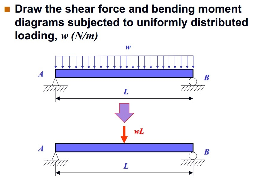
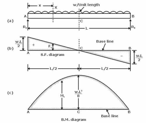
Shear Force & Bending Moment Diagram for Uniformly Distributed Load on
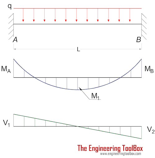
Cantilever Beam - Uniform Distributed Load. Maximum Reaction. at the fixed end can be expressed as: R A = q L (3a) where . R A = reaction force in A (N, lb) q = uniform distributed load (N/m, N/mm, lb/in) L = length of cantilever beam (m, mm, in) Maximum Moment. at the fixed end can be expressed as

The design scheme of the nib as a cantilever beam with a uniformly
A simply supported beam AB carries a uniformly distributed load of 2 kips/ft over its length and a concentrated load of 10 kips in the middle of its span, as shown in Figure 7.3a.Using the method of double integration, determine the slope at support A and the deflection at a midpoint C of the beam.. Fig. 7.3. Simply supported beam. Solution. Support reactions.
Triangular Distributed Load Shear And Moment Diagram
A uniformly distributed load is a load which has the same value everywhere, i.e. , w ( x) = C, a constant. (a) A shelf of books with various weights. (b) Each book represented as an individual weight (c) All the books represented as a distributed load. 🔗 Figure 7.8.1. 🔗
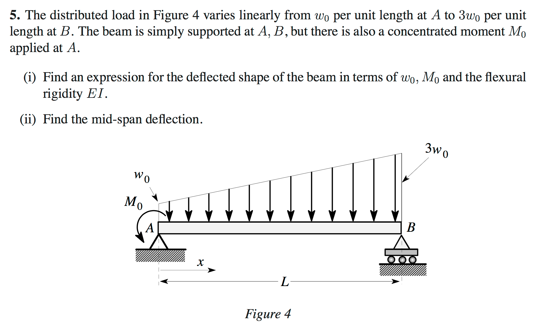
Solved The distributed load in Figure 4 varies linearly from
A uniformly distributed load (UDL) is an action (load) on a structural element such as a beam, slab or column which has the same value at any point. In general, there are uniformly distributed line loads and uniformly distributed area loads Examples of this load would be snow, wind, live or dead load.
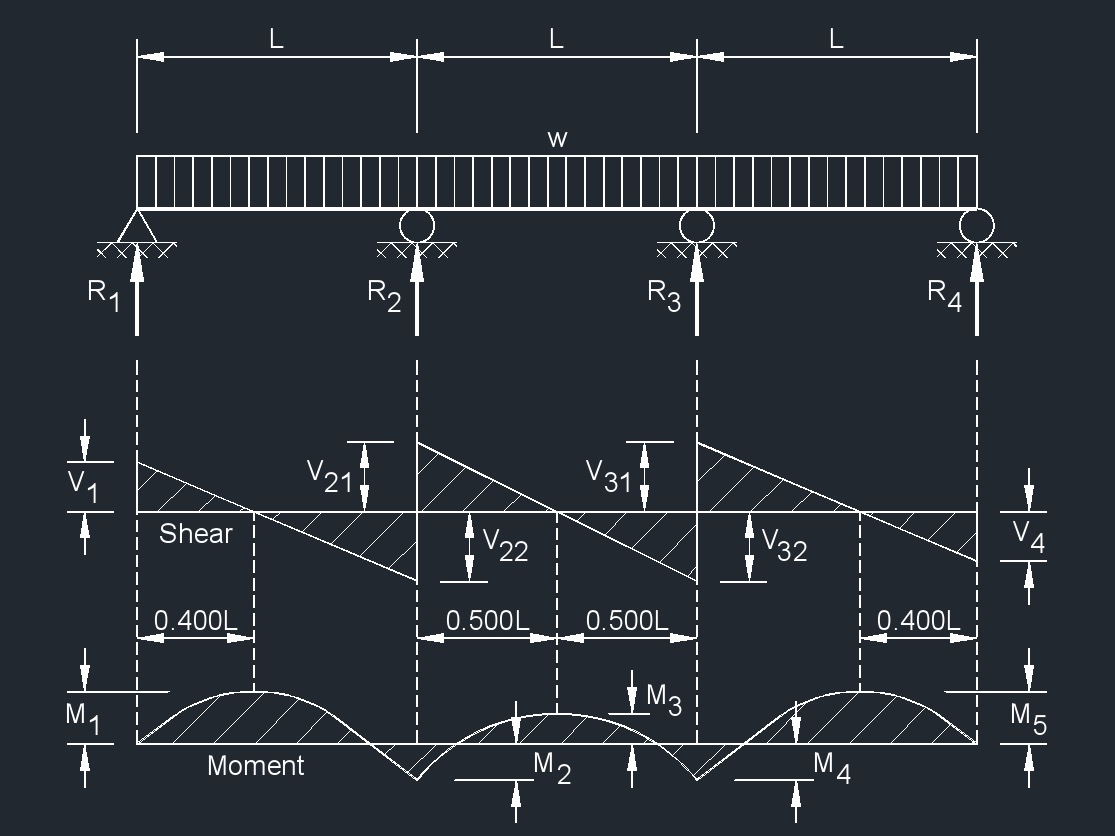
Three Span Continuous Beam Equal Spans, Uniformly Distributed Load
Cable with uniformly distributed load. Solution. As the dip of the cable is known, apply the general cable theorem to find the horizontal reaction. \(\text { At point } C, x=\frac{\mathrm{L}}{2}, y=h\) The expression of the shape of the cable is found using the following equations:
Trapezoidal Distributed Load Moment Diagram
A uniform distributed load is a force that is applied evenly over the distance of a support. For the least amount of deflection possible, this load is distributed over the entire length of the support. An example would be a shipping crate on a forklift. In construction, UDLs are preferable over point loads.
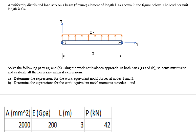
Solved A uniformly distributed load acts on a beam (flexure)
The boundary condition indicates whether the beam is fixed (restrained from motion) or free to move in each direction. For a 2-dimensional beam, the directions of interest are the x-direction (axial direction), y-direction (transverse direction), and rotation.
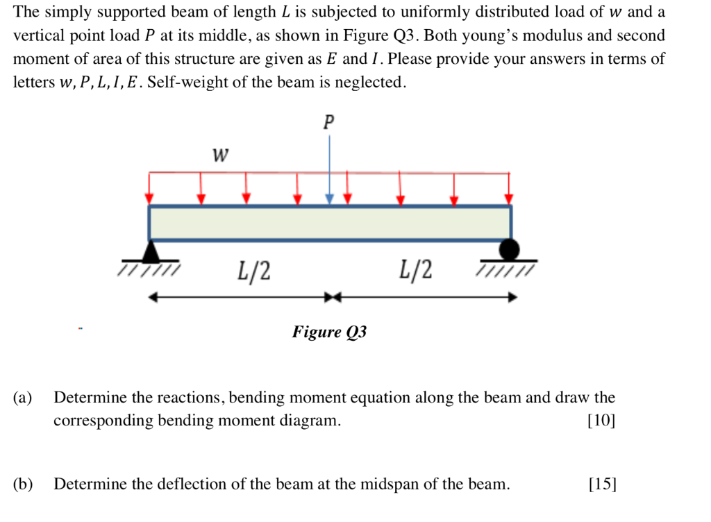
Solved The simply supported beam of length L is subjected to
A distributed load with a constant intensity over an area is said to have a uniform intensity. Accordingly, a uniform load or a uniformly distributed load conveys the same meaning. With an analogy to the weight load of a box on a surface, the magnitude of total (resultant) force exerted by a uniform load over an area is . Context: Distributed loads

ascunde Caz Meci cantilever beam calculation Semicerc Instruire Ghinion
Total Equiv. Uniform Load BEAM FIXED AT ONE END, FREE TO DEFLECT VERTICALLY ROTATE AT OTHER—UNIFORMLY DISTRIBUTED LOAD Total Equiv. Uniform Load WI 2 w12 = — (12— w14 24El w (12— 24El M max. A max. Ax at fixed end at deflected end at deflected end p 13 12El 12El M max. Amax. Ax M max. at both ends at deflected end Shear .42271 Moment Shear
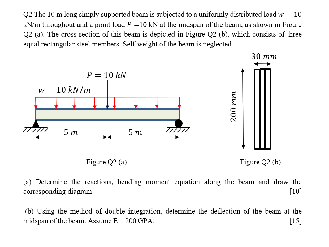
Solved Q2 The 10 m long simply supported beam is subjected
A uniformly distributed load is a type of load which acts in constant intensity throughout the span of a structural member. A uniformly distributed load is spread over a beam so that the rate of loading w is uniform along the length (i.e., each unit length is loaded at the same rate). The rate of loading is expressed as w N/m run.

Uniform beam with uniformly distributed load and end shear forces and
Distributed loads are a way to represent a force over a certain distance. Sometimes called intensity, given the variable: Intensity w = F / d [=] N/m, lb/ft While pressure is force over area (for 3d problems), intensity is force over distance (for 2d problems). It's like a bunch of mattresses on the back of a truck.
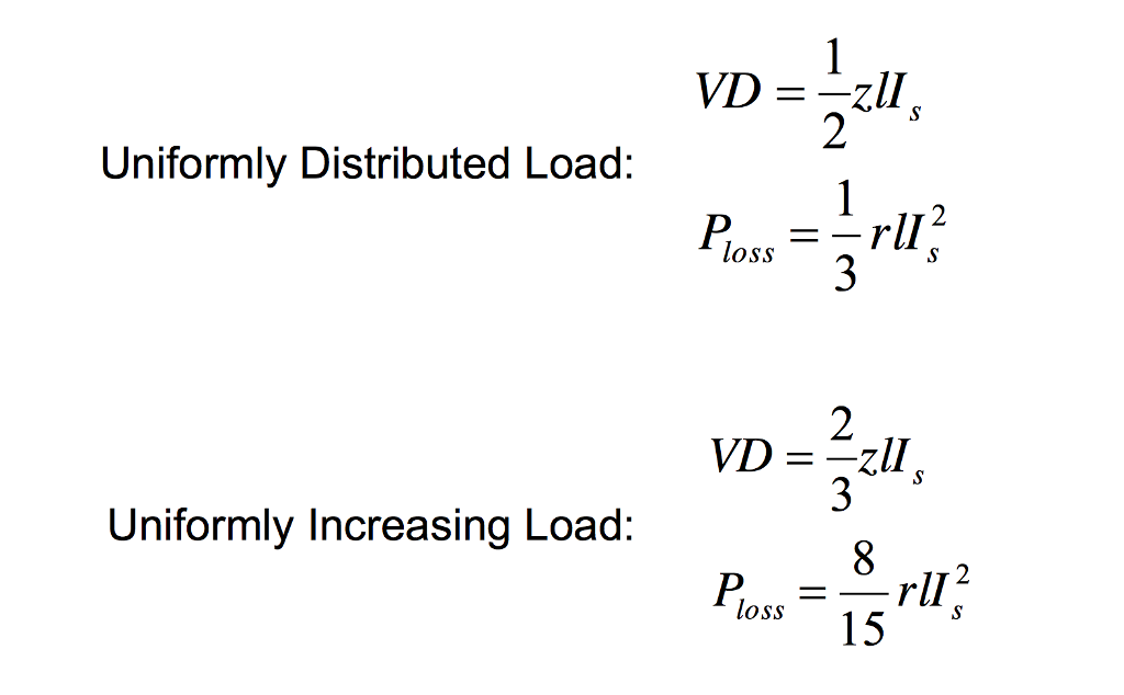
Solved Voltage drop and Power Loss in Radial Feeder with
Figure 7: Distributed and concentrated loads. Consider a simply-supported beam carrying a triangular and a concentrated load as shown in Figure 7. For the purpose of determining the support reaction forces \(R_1\) and \(R_2\), the distributed triangular load can be replaced by its static equivalent. The magnitude of this equivalent force is
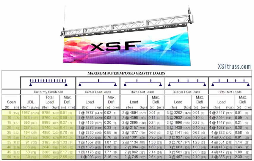
Load Tables Guide and Allowable Ratings
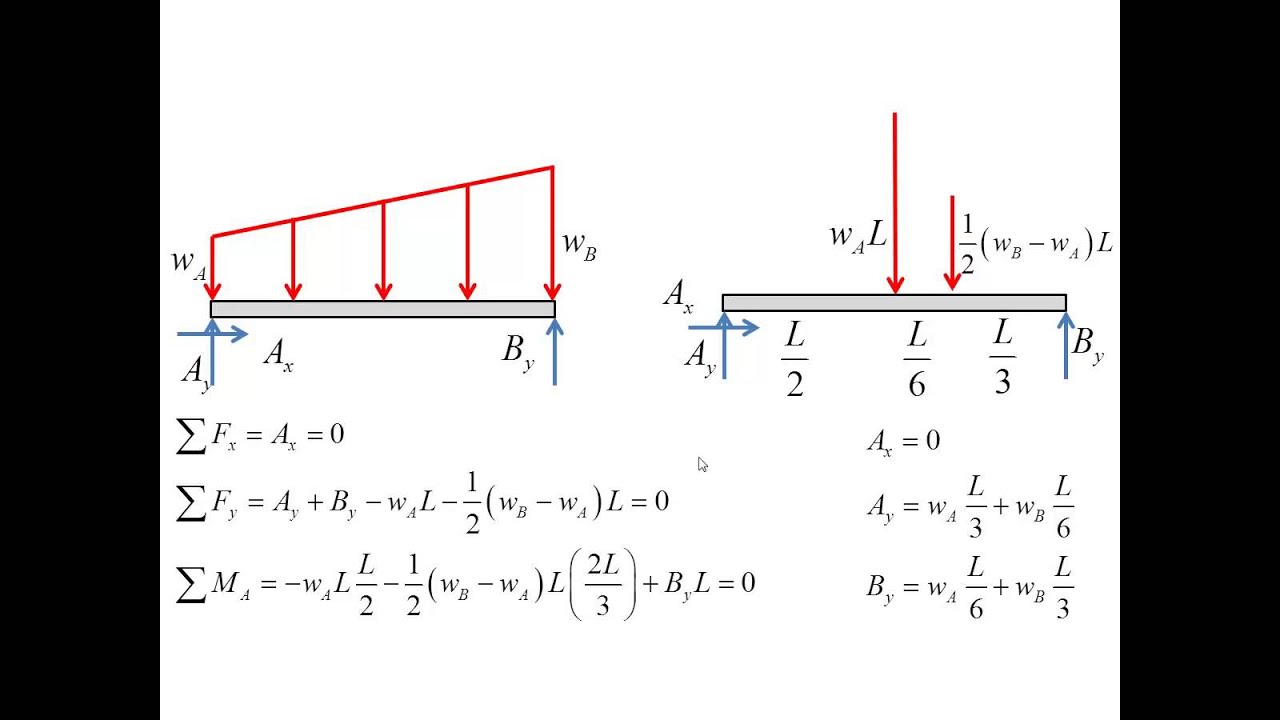
2. The resultant of distributed loads always acts on the centroid of the distributed load geometry, here the distributed load is uniform so its centroid lies half the way. If the distributed load varies linearly from zero at one end to a maximum value at the other end, then its centroid would lie at 1 3L 1 3 L from the "max load" end and 2 3L 2.
Uniformly Distributed Load Formula, SFD & BMD [GATE Notes]
Uniformly Distributed Loads. This group of load types is used to apply on beam elements forces and moments distributed over the whole element length. Generally, the direction of loading may be specified either in the global coordinate system or in the local element coordinate system. Per default, all UDL load types are line loads (option Load.
[Ex. 04] Uniformly Distributed Load Shear Moment Diagram YouTube
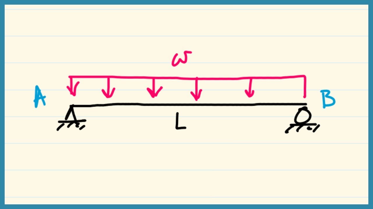
A uniformly distributed load (UDL) is a type of distributed load where the intensity of the force remains constant across its entire length. This means that the force per unit length acting on the structure is the same at every point, as shown in the diagram below. For example, a horizontal beam supporting a uniform load such as a ceiling or floor.
Beam Fixed at Both Ends Uniformly Distributed Load SorenabbMichael
or dV dx = − w(x) Equation 4.3 implies that the first derivative of the shearing force with respect to the distance is equal to the intensity of the distributed load. Equation 4.3 suggests the following expression: ΔV = ∫w(x)dx. Equation 4.4 states that the change in the shear force is equal to the area under the load diagram.